- Jarvis - The DIY robot
- Basic robotic control software with ROS 2
- Navigation and mapping with ROS 2
- Obstacle avoidance using machine learning
Jarvis - The DIY robot
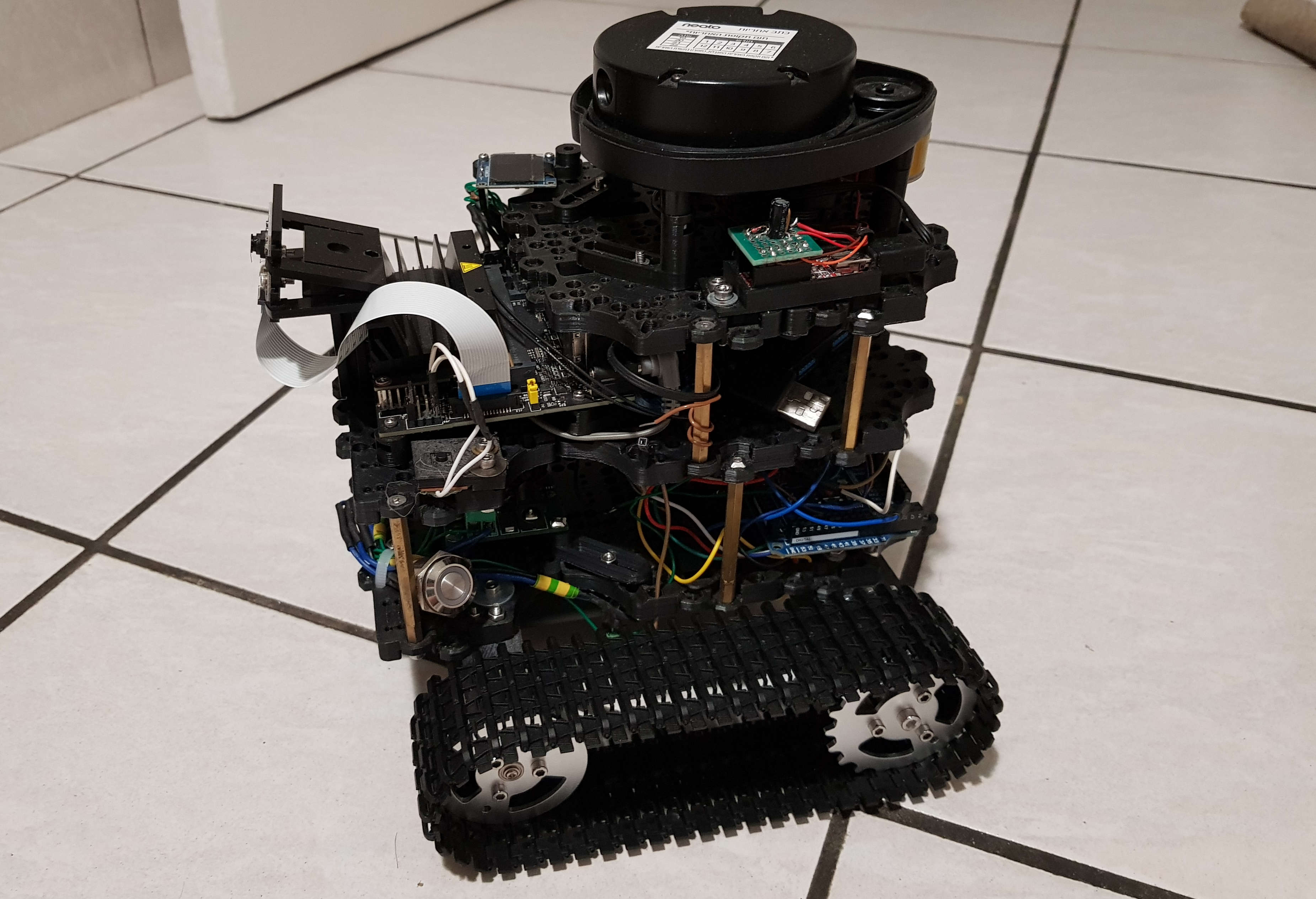
Jarvis is the upgraded version of my first DIY mobile robot, Dolly. My goal in this DIY project is to make a low-cost yet feature-rich ROS (Robot Operating System) based mobile robot that allow me to experiment my hobby work on autonomous robot. To that end, Jarvis is designed with all the basic features needed. To keep the bill of material as low as possible, i tried to recycle all of my spare hardware parts.
This booklet will walk you through all the basic building steps of the robot. both on hardware and software (ROS).
Specification
- Robot's chassis is 3D printed, the chassis's plate design is borrowed from the design of ** Turtlebot 3** which is a smart design. The other hardware parts, however, are completely different from the Turtlebot 3.
- IMU sensor with 9 DOF (accelerometer, magnetometer and gyroscope) for robot orientation measurement
- Two DC motors with magnetic encoders using as wheels and odometer
- Arduino Mega 2560 for low level control of the robot
- NVDIA Jetson nano with embedded Linux for high level algorithm and network communication. The ROS middle-ware on top of the Linux system offers a powerful robotic software environment
- A 360 degree Neato LiDAR (laser scanner) up to 6 m range
- A 8 Mega pixel camera (Raspberry PI camera)
- Adafruit Motor shield V2 for motor controlling
- 10000 Mah battery
- ADS1115 analog sensor to measure and monitor battery usage
- 0.95" (128x64) mini OLED display
- Wifi + Bluetooth
- The robot can be tele-operated using a bluetooth controller such as a PS4 controller
Components detail
The robot is built on 3 main layers:
Bottom layer
The first layer consists all the low-level components for robot controller:
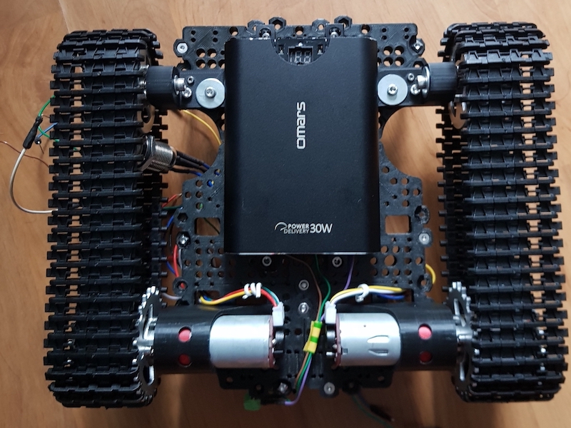
On the bottom of of the first layer:
- Track wheels
- Two 6-12v DC motors with magnetic wheel odometry sensor
- 10000 MAh battery
All low-level components for robot controlling are mounted on the top of the first layer:
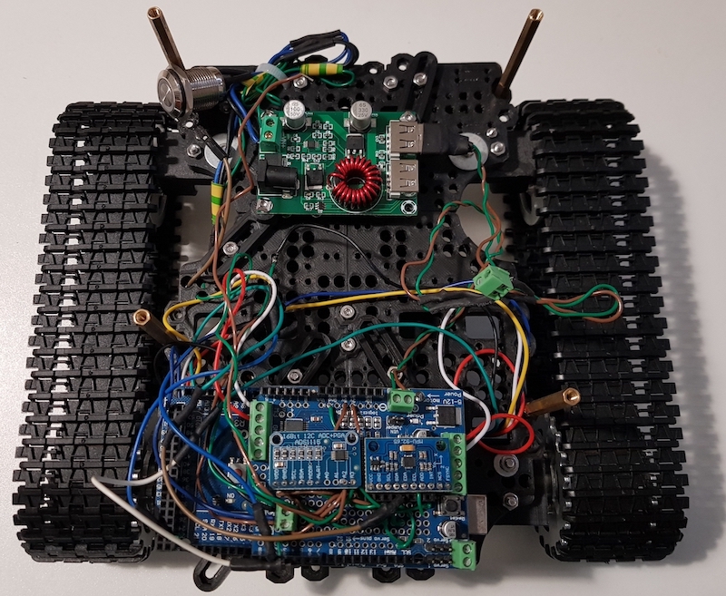
- Step down voltage regulator that provide two independent outputs up to 3A:
- 6V/3A that powers two DC motors
- 5V/3A for all logic circuits
- Arduino Mega 2560 + Adafruit Motor shield V2: for motor controlling, raw sensor reading/processing and hardware interrupt
- 9DOF IMU sensor including: accelerometer, gyro, magnetometer
- ADS1115 analog sensor to measure and monitor battery voltage
- Power buttons
Middle layer
The central high-level computer, NVDA Jetson nano is mounted on the middle layer:
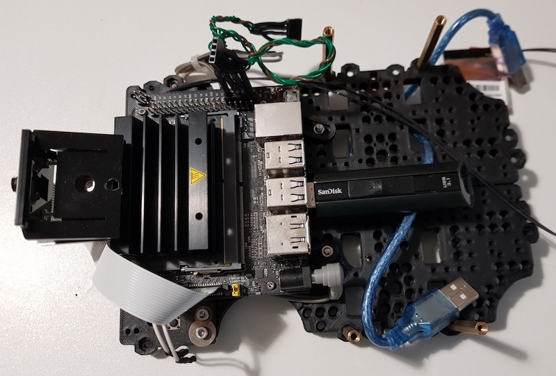
Base components:
- Jetson Nano with Linux and ROS installed
- 8 M pixels camera sensor
- 128 GB USB based SSD for operating system and storage
- Wifi/ Bluetooth
The Jetson Nano board connects to the Arduino board via USB-TTL link for control commands and sensor data collecting. This USB link is also used to power the Arduino board and its attached sensors.
Top layer
The Neato LIDAR sensor can be found on the top layer of the robot:
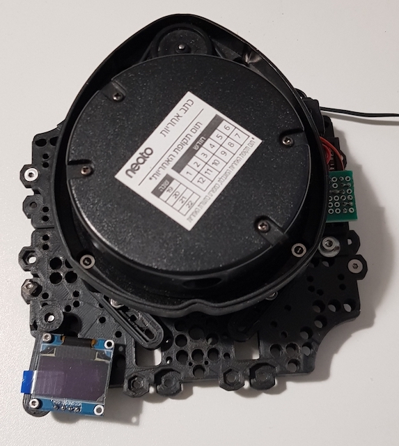
This sensor provide the robot with a laser vision of 360 degree and up to a distance of 4 meter.
The 0.95" (128x64) mini OLED display is also mounted on this layer to display the system statistic
Printed 3D models
The following is the 3D model of printed parts used to assembly the Robot chassis (borrowed from the Turtlebot 3 design)
Applications
- Localization and mapping (SLAM)
- Obstacle avoidance
- Autonomous navigation
- Robot perception algorithms with LIDAR sensor and camera
- Much more...
SLAM mapping with Jarvis
Jarvis is controlled by ROS, the following video demonstrates the use case where the robot is used to performed the localization and mapping task using its available sensors such as odometry, LIDAR, IMU...
Comments
The comment editor supports Markdown syntax. Your email is necessary to notify you of further updates on the discussion. It will be hidden from the public.