- Jarvis - The DIY robot
- Basic robotic control software with ROS 2
- Navigation and mapping with ROS 2
- Obstacle avoidance using machine learning
Arduino Firmware
The arduino firmware on the one hand implements the JETTY protocol for communicating with ROS and on the other hand takes care of all low-level hardware communication including:
- Reading of battery voltage from the ADS1115 16-Bit ADC sensor
- Reading of 9DOF IMU sensor data from MPU 9250 IMU sensor
- Reading of raw odometry data from two motor magnetic encoders. Reading these sensor involves the use of 4 Arduino interruption pins (detail below)
- Control two motor via Adafruit Motor Shield V2
Work flow
The work flow of the Arduino firmware can be found on the following figure:
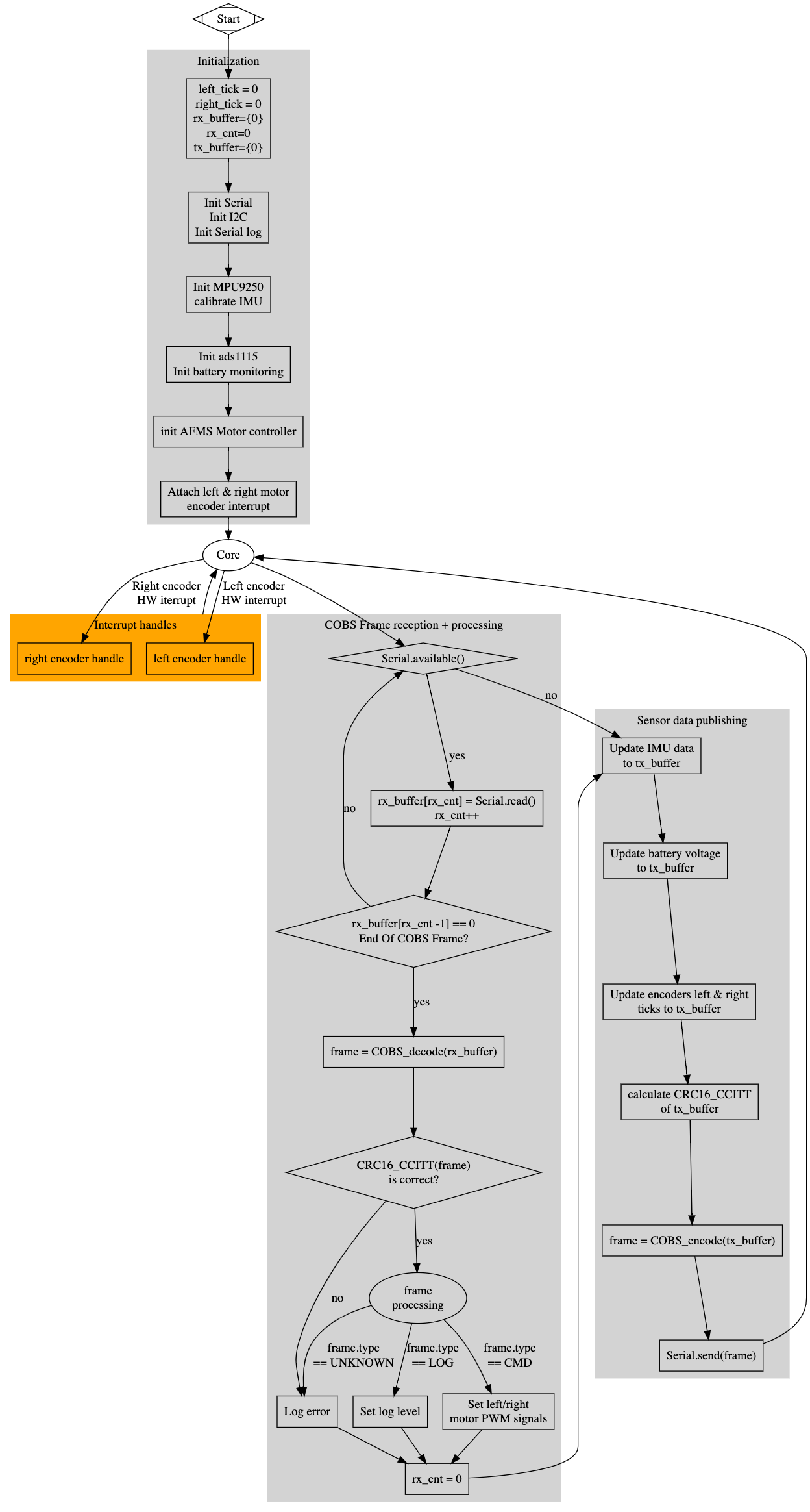
Basically, after the initialization, the firmware performs three principal routines:
Hardware interruption routine
The first routine is the hardware interruption routine which has the highest priority. This routine is triggered by the micro-processor upon the value changing event on one of 4 interruption pins. It allows to read the motor encoder values, which are lately used by ROS to estimate the robot position (Dead Reckoning).
Detail on the odometry data reading is presented in the next sub section.
Reception routine: COBS Frame reception and processing routine
This routine handles the high level data reception from ROS via the JETTY protocol, it monitors the input serial link, and perform the following task:
- Frame synchronization
- Frame reading into internal buffer
- Validating, decoding and processing a frame once its reception is done
The implementation of frame reception and processing is pretty forward as shown in the schema above. The Arduino firmware handles two kind of frame:
- The log frame: configures the log level on the Arduino side
- The command frame: controls the two motors speed and direction. The frame data consists of two integers corresponding to the speeds of the left and right motor. Negative/positive value means the motor going backward/forward.
Detail on the motor controlling is presented in sub section.
Transmission routine: Sensor data publishing
This routine collects all the sensor data and publishing this data to ROS via the JETTY protocol. The sensor data consists of:
- Odometry data which is already collected by the interruption routine
- Battery voltage collected from the ADS1115 16-Bit ADC sensor (detailed in subsection)
- IMU sensor data collected from the MPU 9250 IMU sensor (detailed in sub section)
All the sensor data is encoded in a 47 bytes COBS data frame before sending to ROS via the serial link. The data is published with the frequency of around 100Hz.
Final Firmware Implementation
Information on workspace setup can be found here
The implementation of JETTY on arduino can be found in ~/workspace/arduino/JETTY, the sketch depends on some external libraries that can be installed using arduino-cli.
Install all the dependencies libraries:
arduino-cli lib install "Adafruit Motor Shield V2 Library"
arduino-cli lib install "Adafruit ADS1X15"
Note the MPU9250 library header is included directly in the repository, so no need to install it
Build the JETTY sketch:
cd ~/workspace/arduino/
arduino-cli compile --fqbn arduino:avr:mega JETTY
Then upload the sketch to the Arduino:
arduino-cli upload -p /dev/ttyACM0 --fqbn arduino:avr:mega JETTY
JETTY will run on the Arduino and start transferring sensor data. Note that The board will be reset automatically when the ROS endpoint connects to the serial link.
Comments
The comment editor supports Markdown syntax. Your email is necessary to notify you of further updates on the discussion. It will be hidden from the public.