- Jarvis - The DIY robot
- Basic robotic control software with ROS 2
- Navigation and mapping with ROS 2
- Obstacle avoidance using machine learning
Odometry data reading from magnetic encoder
Jarvis has two motors with magnetic encoder feedback, each encoder has two pins that are connected to two interrupt pins on the Arduino board (4 pins in total). Normal GPIO pins cannot be used in this case since it will be too slow to capture all the value changes of the encoder in the main loop. Hardware interruption routine is more appropriate in this situation. The table below shows the physical wiring between Arduino Mega interrupt pins and Motors encoder pins:
| Arduino | Encoder |
|---|---|
| 2 | Right encoder A |
| 3 | Right encoder B |
| 4 | Left encoder A |
| 22 | Left encoder B |
Each motor has two encoder pins connected to two hall effect sensors which allow to measure "the voltage difference (the Hall voltage) across an electrical conductor, transverse to an electric current in the conductor and to an applied magnetic field perpendicular to the current". This effect is produced when the motor rotates thanks to the 6 poles magnetic disc attached to the shaft of the motor.
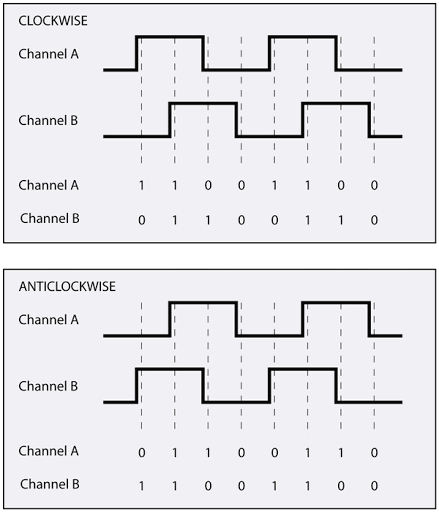
The two hall effect sensors produce two square wave outputs which are 90 degrees out of phase. This is called a quadrature output. This out of phase allows us to know both the magnitude and the direction of the motor’s rotation:

If output of encoder A pin is ahead of output of encoder B pin, then the motor is turning forward. If output A is behind B, the motor is turning backward. Pretty simple.
Implementation of the interruption routine is simple by following exactly this principle, the following example snippet show the reading of left odometry data:
static int left_motor_tick = 0;

static void left_encoder_event()
{
    if (digitalRead(LM_ENCODER_A) == HIGH)
    {
        if (digitalRead(LM_ENCODER_B) == LOW)
        {
            left_motor_tick++;
        }
        else
        {
            left_motor_tick--;
        }
    }
    else
    {
        if (digitalRead(LM_ENCODER_B) == LOW)
        {
            left_motor_tick--;
        }
        else
        {
            left_motor_tick++;
        }
    }
}

// In the setup method

void setup() {
    ...
    attachInterrupt(digitalPinToInterrupt(LM_ENCODER_A), left_encoder_event, CHANGE);
    ...
}
The odometry data is a part of the 47 bytes COBS data frame which will be sent to ROS for high level control.
Comments
The comment editor supports Markdown syntax. Your email is necessary to notify you of further updates on the discussion. It will be hidden from the public.