JETTY: Jarvis Serial to ROS-2 Transport Layer
As the arduino is used for low-level communication with actuators/sensors. We need a software transport layer on top of the physical serial link (Jetson - Arduino) to stream (sensor) data/command from Arduino to ROS 2 and vice versa. On Dolly (my previous robot version), which used ROS 1, this was handled by Rosserial, a protocol for wrapping standard ROS serialized messages and multiplexing multiple topics and services over a serial link. On ROS 2, however, Rosserial is not available. Other alternative solutions exist but are not mature enough, some implementations require more computational resource which exceeds the capability of the Arduino Mega 2560.
So i decided to implement a dedicated transport layer for Jarvis called JETTY (Jarvis SErial to ROS-2 TransporT LaYer). I do not aim at a generic protocol for ROS to serial communication like ROS serial. Instead, the implementation of the transport layer should be specific only to the robot. However, the protocol must be easy to extend to adapt to any future upgrade of the robot such as adding more sensor/actuators.
Requirements on the transport layer:
- The transport layer must allow to stream data in form of frames (fixed size or not)
- Simple but reliable, unambiguous packet framing protocol, frame should be easy to identify
- Fast frame synchronization: When an endpoint (Arduino or ROS) connects to the Serial link in the middle of the data streaming, frame synchronization should be fast while minimizing the frames lost in the synchronization phase
- Frame should be verified using checksum before being consumed by an endpoint
- Packet framing overhead is allowed but need to be minimized
- The algorithms should be easy to implement and computationally inexpensive on both Jetson and Arduino
Brief, we need an efficient and reliable delimiting/synchronization scheme to detect the frame with short recovery time.
The most simple technique is to use a header/pattern to mark the start and/or end of frame and validate frame content using checksum. However, this method is not very reliable since the header/pattern is not alway unique and distinct from frame data. Frame desynchronization may occurs often and it is hard to quantify the desynchronization frequency, as well as the recovery time.
One possible option is to limit the protocol to only use the printable characters (text) in its framing scheme. The checksum can be omitted since the text data may has it own format (e.g. JSON,XML, etc.) and can be validated by the end-point applications. Non printable character, such as null terminal, therefore can be used as frame delimiter. Most of the time, when an end-point joins the communication at the middle of the stream, the frame synchronization can be fast and predictable (at the next occurrence of the delimiter character). This option may be reliable, and is easy to debug but it is not very suitable in the context of our application where data is in binary mode (sensor values or actuator commands). Additional processing power and memory are required to (1) convert sensors data to formatted text (serializing), and (2) to parse text frame to internal application data structure (materializing). It may not be the problem with the Jetson Nano, but implementing such serialization/materialization mechanism on the Arduino, where the memory and processing power are limited, is a real challenge, especially with the real-time constrain.
Bit marking could be another solution for binary data framing. There are two options:
- 9th Bit marking: An additional bit is appended to each transfered byte, with data byte is marked with bit value 0 and frame delimiter is marked with bit value 1. This allows a reliable framing mechanism with fast recovery time. However, its requires hardware support.
- 8th bit marking: Same principle as 9th bit marking but don't require hardware support, the 8th bit of each transfered byte is used for marking, leave only 7 bit for each data word. This method introduces data overhead and requires a mechanism to encode/decode data bytes to 7 bits word.
Last but not least, Byte stuffing is a process that transforms a sequence of data bytes that may contain 'illegal' or 'reserved' values (such as frame delimiter) into a potentially longer sequence that contains no occurrences of those values. The extra length of the transformed sequence is typically referred to as the overhead of the algorithm.
One of the most efficient byte stuffing implementations is is called Consistent Overhead Byte Stuffing (COBS). It is "an algorithm for encoding data bytes that results in efficient, reliable, unambiguous packet framing regardless of packet content, thus making it easy for receiving applications to recover from malformed packets" (Wikipedia). The overhead introduced due to frame encoding is consistent and quantifiable. The implementation is simple and fast which is suitable for resource constrained system such as Arduino.
Verdict:
On all methods presented above, Consistent Overhead Byte Stuffing offers the best compromise to all of my requirements on the protocol, especially when couping with a data validation method. For data checksum, a Cyclic Redundancy Check (CRC) should be enough to validate and detect frame errors. Different CRC algorithms are available for serial communication.
The next sub-sections will detail on the COBS and CRC algorithms which are implemented in JETTY.
Consistent Overhead Byte Stuffing
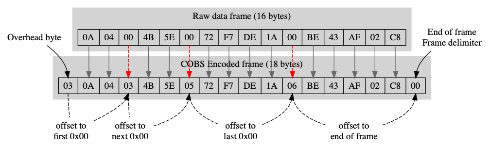
Detail on the algorithm and its implementation can be found on the wikipedia page. In brief, COBS uses the byte 0 as frame delimiter and encodes an arbitrary array of data bytes range [0,255] into bytes in the range [1,255]. As shown in the figure, this can be achieved by:
- Adding an overhead byte to the beginning of the frame, the value of this byte is the offset to the first 0 data byte
- All 0 bytes in the data array is encoded with the offset to the next 0 byte or end of frame (from that position)
- If the offset to the next 0 bytes is greater than 255, then an overhead byte is added to the offset 255 (from the current position), this byte point to the next 0 byte
As we can see, the overhead is consistent since an overhead byte is added for each 254 non-zero bytes of data (if the data length is more than 254 bytes). The encoded data has the same size as the original (except the added overhead byte).
The decoding of encoded frame is straight forward by replacing offset bytes with zero and remove the overhead bytes.
The implement of the algorithm is simple, the encoding/decoding processes are fast and computationally inexpensive.
Frame verification with CRC-16
Cyclic Redundancy Check is a well-known method for detecting accidental changes to raw data in network application. The CRC calculation is straight forward, raw data is treated by the CRC algorithm as binary number, This number is divided by another binary number called the polynomial. The remainder of the division is the checksum. This checksum will be appended to the transmitted message/frame (hence the term redundancy). The receiver of the message/frame divides it (including the CRC value) by the same polynomial. If the result is zero, then there is no error in the transmission, otherwise, the message/frame is considered as error.
A CRC is called an n-bit CRC or CRC-n when the checksum value is n bits long. For a given n, multiple CRCs are possible, each with a different polynomial. Such a polynomial has highest degree n, which means it has n + 1 terms. In other words, the polynomial has a length of n + 1; its encoding requires n + 1 bits.
Example: The simplest error-detection system, the parity bit, is in fact a 1-bit CRC: it uses the generator polynomial x + 1 (two terms), and has the name CRC-1.
CRC algorithm is simple and easy to implement and is good at detecting common error during data transmission. However, the selection of the polynomial is the most important part of implementing the CRC algorithm. The polynomial must be chosen to maximize the error-detecting capabilities while minimizing overall collision probabilities.
Fortunately, we do not need to generate ourself a polynomial that works well on our serial link. There is a list of standard polynomials that are suitable for different kinds of communication.
For my implementation, i used CRC-16-CCITT which is good for serial communication. The following polynomial is used:
$$x^{16}+x^{12}+x^5+1$$
Frame description
As the transport layer is application specific, the frame format depends on what kind of data we want to transfer on the serial link:
- Sensor data sent from the Arduino to the ROS middleware, these values include: IMU data, battery voltage, odometry sensor data (left and right)
- Log messages from the Arduino to the ROS middleware for debug purpose
- Commands from ROS to Arduino for low-level robot control (such as motors control)
All raw frames (before COBS encoding) follow the following template:
----------------------------------------------------------
| 1 bytes frame type  | n-bytes data..... | 2 bytes CRC  |
----------------------------------------------------------
Conventions:
- With COBS, there is literally no constrain on the frame size, but to facilitate the implementation, in this context, the frame size is limited to 255 bytes or maximal 252 bytes data (which is largely enough for our purpose).
- Data value (except text string) is sent in network byte order (big-endian)
- The 2 bytes CRC value is the checksum of the rest of the frame which includes 1 bytes frame type + n bytes data (n+1 bytes).
Given the data description above, frame can be classified into 3 types:
Data frame
This kind of frame is transfered only from Arduino (transmitter) to ROS (receiver), sensor data is packaged in a fixed size frame of 47 bytes in the following format:
--------------------------------------------------------------------------------------------------------------
| 0x0 |Raw IMU data (36 bytes) | Baterry (4 bytes)| left odom. (2bytes) | right odom. (2 bytes) | 2 bytes CRC  |
--------------------------------------------------------------------------------------------------------------
Frame type is 0x0. The raw IMU data contains values in the following order:
| Field | Size (bytes) |
|---|---|
| Gyro X | 4 |
| Gyro Y | 4 |
| Gyro Z | 4 |
| Accel. X | 4 |
| Accel. Y | 4 |
| Accel. Z | 4 |
| Mag. X | 4 |
| Mag. Y | 4 |
| Mag. Z | 4 |
Log frame
The log frame follows the following format:
-----------------------------------------------------------------
| 0x1 | log level (1 byte) | n bytes log message | 2 bytes CRC  |
-----------------------------------------------------------------
Specification:
- Frame type is 0x1
- Log levels:
LOG_FATAL (0x0),LOG_ERR (0x1),LOG_WARNING (0x2),LOG_INFO (0x3)andLOG_DEBUG (0x4) - Log frames are variable in size, however, since the maximal frame size is limited to 255 bytes, log message must not be more than 251 characters and can be empty (
n=0) - A frame represents an entire log message
The log frame is sent by both endpoints (transmitters) (Arduino and ROS) with different purposes:
- Arduino: log frames are used to send log messages from Arduino to ROS
- ROS: log frames are used to set the log level on the Arduino endpoint, in this case the log message is empty (
n=0)
Command frame
The fixed size command frames are transfered only by ROS (transmitter) and are used to send commands to Arduino (receiver) for motors control, it follows the following format:
--------------------------------------------------------------------------------
| 0x2 | left motor speed (2 bytes) | right motor speed (2bytes) | 2 bytes CRC  |
--------------------------------------------------------------------------------
Where left/right motor speeds are the PWM signal values that will be written to the motor controller.
The detail on the implementation of the transport layer on both Arduino and ROS is presented on the next sub-sections.
Comments
The comment editor supports Markdown syntax. Your email is necessary to notify you of further updates on the discussion. It will be hidden from the public.