- Jarvis - The DIY robot
- Basic robotic control software with ROS 2
- Navigation and mapping with ROS 2
- Obstacle avoidance using machine learning
Battery monitoring with ADS1115 16-Bit ADC sensor
The ADS1115 16-Bit ADC sensor is a hight precision 16 bit ADC with sampling rate up to 860 samples/second. The sensor can be controlled via the I2C interface. The chip can be configured as 4 single-ended input channels, or two differential channels. The sensor even includes a programmable gain amplifier, up to x16, to help boost up smaller single/differential signals to the full range.
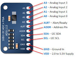
For our purpose, we use one differential channels (or two input channels) to measure the battery voltage, leave 2 input channels for future use. Note that the sensor offers input ranges up to 6V. However Jarvis battery outputs up to 12,6v. Unless you want to fry the sensor and damage the Arduino (and probably the Jetson Nano). We cannot connect directly the battery VCC and GND to the sensor input.
History of Jarvis battery design: Initially, a 10Ah power bank is used to power the system, both for actuators (motors) and control logic. The power bank is modified to be able to output up to 4.2V* 4 cells = 16,8V, which is required by the step down converter (minimum input is 9V). Lately, one of the 4 power cells is dead by accident... and is removed from the power bank, leaves 3 cells remaining with maximum output of 12,6v.
We need, therefore, a solution to reduce the input voltage of the ADC input channels in the 6V range. A classic voltage divider solution can work in this case:
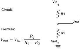
$$V_{in}=V_{out}*ratio$$ $$ratio=\frac{R_1+R_2}{R_2}$$
With \(V_{in}=12.6\) and \(V_{out}=6\), the minimum value of the \(min(ratio)=2.1\). Any combination of \(R_1\) and \(R_2\) that produces \(ratio>2.1\) would work. However, the voltage divider total resistance, made of \(R_1+R_2\), will determine the current drawn from your battery by the ADC. Lower is the total resistance and more accurate are your readings, higher the resistance and less current is drawn from your battery. Experiment shows that the total resistance value around \(20k\Omega-25k\Omega\) offers a good compromise.
In this case, the chosen values are: \(R_1=16.2k\Omega\) and \(R_1=7k\Omega\) -> \(ratio=3.3\), which means that the max input voltage of the ADC input channel is around 4V. Keep in mind that ratio, since we will need to multiply it by the ADC reading to get the real battery voltage.
Finally the wiring of the battery, the voltage divider the ADS1115 and the Arduino is as follow:
| Battery | Voltage divier | ADS1115 | Arduino |
|---|---|---|---|
| VCC | \(V_{in}\) | ||
| GND | GND | A3 | |
| \(V_{out}\) | A2 | ||
| SDA | SDA | ||
| SCL | SCL | ||
| VDD | VCC | ||
| GND | GND |
Note: the GND of the battery and the Arduino should be connected together.
The sensor data reading implementation is pretty simple since the library for communicating with the sensor is already available.
Example of reading voltage:
#include <Adafruit_ADS1015.h>
#define ADS_MULTIPLIER 3.0F
#define RATIO 3.3F

// init the sensor via i2c
ads.begin(); //  GAIN_TWOTHIRDS
...
// reading voltage
uint16_t data = ads.readADC_Differential_2_3();
float voltage = data*ADS_MULTIPLIER*RATIO;
...
The battery voltage is a part of the 47 bytes COBS data frame which will be bring up to ROS for high level control.
Mapping voltage to battery percentage
This section is inspired by the work of the Arduino Battery Sense library
Note that the mapping functions presented in this section are not implemented in the Arduino firmware. They are part of the ROS 2 implementation
This section may be lately moved to the ROS 2 implementation documentation...
Now that we can read the battery voltage, how we correctly monitor it. The idea is to used the read voltage to guess the remaining battery capacity, given the safe bound voltage (upper \(v_{max}\) and lower \(v_{min}\) ) of the battery.
The simplest assumption is to consider that the battery capacity (percentage) is linearly correlated to its voltage:
$$c=\frac{x\cdot100}{y }$$
With \(x=v_{read}-v_{min}\) and \(y=v_{max}-v_{min}\)
In reality, this assumption is not correct since the relation between voltage and capacity depends on many factors: battery chemistry, current draw, temperature, age, etc. This relation is better represented by a curve. According to the author of the Arduino Battery Sense library, this curve can be modeled by (but not limited to) the following mapping functions
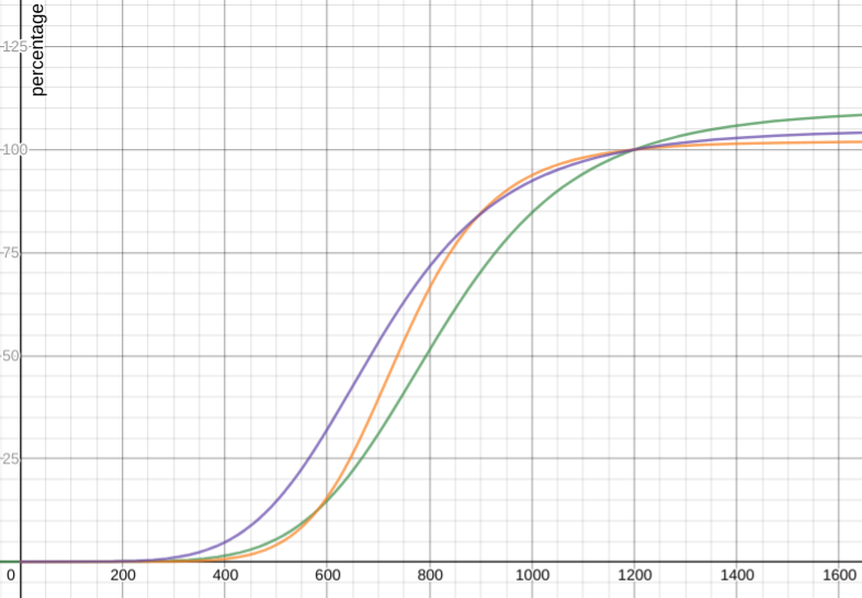
Symmetric sigmoidal approximation
$$c=110-\frac{110}{1+\left(\frac{1.468\cdot x}{y}\right)^{6}}$$ (green)
$$c=102-\frac{102}{1+\left(\frac{1.621\cdot x}{y}\right)^{8.1}}$$ (orange)
$$c=105-\frac{105}{1+\left(\frac{1.724\cdot x}{y}\right)^{5.5}}$$ (purple)
Asymmetric sigmoidal approximation
$$c=101-\frac{101}{(1+\frac{1.33\cdot x}{y}^{4.5\ })^{3}}$$
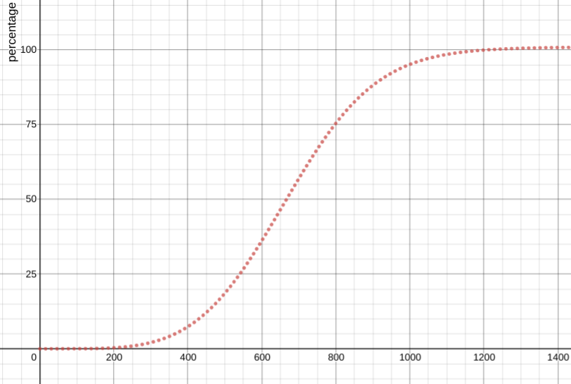
Among these mapping functions, the asymmetric sigmoidal approximation function is the closest model to the battery voltage/capacity relationship in reality.
This function is used in the ROS implementation to calculate the battery capacity.
Comments
The comment editor supports Markdown syntax. Your email is necessary to notify you of further updates on the discussion. It will be hidden from the public.